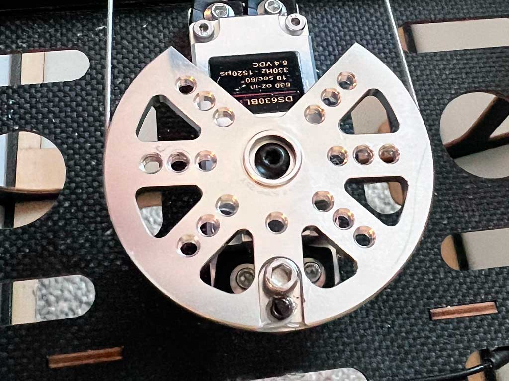
This heavy duty pulley is CNC-machined from a solid billet of 7075-T6
aircraft
aluminum, broached for the ISO25 spline (25T ø6mm). Installation is
axially on the 6mm diameter, 25T-spline shaft (lightly greased), and
secured, with M3
Allen-head machine-thread bolt. Disassembly is the reverse, begin by
removing the M3 bolt securing the leader cable to the pulley, then the
M3 bolt securing the pulley to the splined output shaft.
What secures
the cable from slipping is the figure of 8 made by the cable and the
supplied bolts. Also included are a pair of cable guards because some
guys are fucking stupid aren't very meticulous
about aligning pull-pull cable runs within
the rotation-plane of the pulley.
So why a pulley? Simple, it's because pull-pull cables won't go slack
transiting from one extreme to the other as much as when using a tiller arm. Only thing to watch out for is a) make sure the control
horns align with the hinges, b) you've snugged the figure of 8, and c) that it's a straight shot from the pick up points on the control horns to the plane of rotation of the pulley (else the cable will slip out of the groove).
And this bit about keeping the cable in alignment with the plane of rotation of the pulley groove
is important because there's no such thing as magic pulleys. If they're
not in alignment, then physics dictates they'll come out of the groove.
And no, this isn't a defect, it's down to physics and how cables work. Unfortunately,
because there are stupid people then we also include a pair of cable
guards. With these, the idea is to at least keep the cable within the
last bit of the groove (this, principally to make slipping the cable back into the groove easy after it does slip out). Basically, then you don't have to root around and find the cable! So use the guards for just in case.
Anyway, your benefit of using a pulley is, unlike
with tiller arms, the lead on the downwind side of the control
surface when using a pulley doesn't tend to go as slack as with the tiller, so you maintain
better control when there is buffeting in the air as the surface remains
rock solid.
Installation is pretty simple. Begin by using a couple of sticks of hardwood
with rubber bands at each end. Slide this down over the rudder and
vertical fin to clamp them into alignment. Next, you're going to make a
continuous loop from the left-side rudder control horn, to the pulley
where it makes a figure-8, and back out to the right-side rudder control
horn.
-
note the figure of the cable makes around the fixed post and how it's
clamped beneath the Allen head
Since you want to sneak up on the proper tension, begin with the
eye-bolts about where you want them in the plastic ball-link and then
unscrew them until maybe just 5 turns is all that holds them in.
Basically, you want to have 6-8 more turns of adjustment to tension the
leader cable without the eye bolt bottoming within the link, understand?
Next . . .
- Radio system on, wheel sub-trimmed so the pulley is at neutral, set transmitter out of the way.
- At leader midway point, make the figure of 8 at the pulley, lightly snug the M3 bolt (but not tight).
- Next, thread each leg of the leader to the right and left side rudder control horns.
- Slide the crimp onto the leader cable, loop through eye, and back through crimp, slide crimp toward eye.
- Repeat for the other side, once again, slide crimp toward the eye until they're about equal on each side.
- Eyeball and confirm servo remains at neutral, and leader hasn't slipped off the pivot point.
- Next, lightly tension cable on one side, now crimp it. Go easy on then tension, we'll snug it later.
- Repeat on the other side.
- Now adjust tension using eye bolt into ball-link until you're happy - not too much though!
- Go back and confirm the figure of 8 looks good and tighten the M3 Allen head bolt.
Finally,
release hardwood sticks holding rudder in alignment with vertical stab.
Now operate rudder with the transmitter and confirm tension throughout
the range.
Make slight adjustments as needed but remember, the tension is carried
on the servo output shaft bearing so don't make it like a guitar string,
leave it lightly tensioned, only. Anyway, if there's a downside of a
continuous loop system it's when you need to slacken or tighten the
leader cable, you must to do
both sides the same amount. Not a big deal in practice.
Note; what usually happens is
after a few flights you'll need to snug it up about 1-2 turns on each side until the system takes a set.
Last thing, a) take a gander at this article about tips for improving your because there's more information about using a pulley, and b) and with respect to
leader cable, the really good
stuff cable-wise is this 7x7 stainless leader available on
Amazon. Similarly, these ball bearing swivels
are readily available with the advantage being you can make adjustments
without the cable twisting. And no, we don't earn an Amazon affiliate fee, so nothing in it for us to refer you to them.

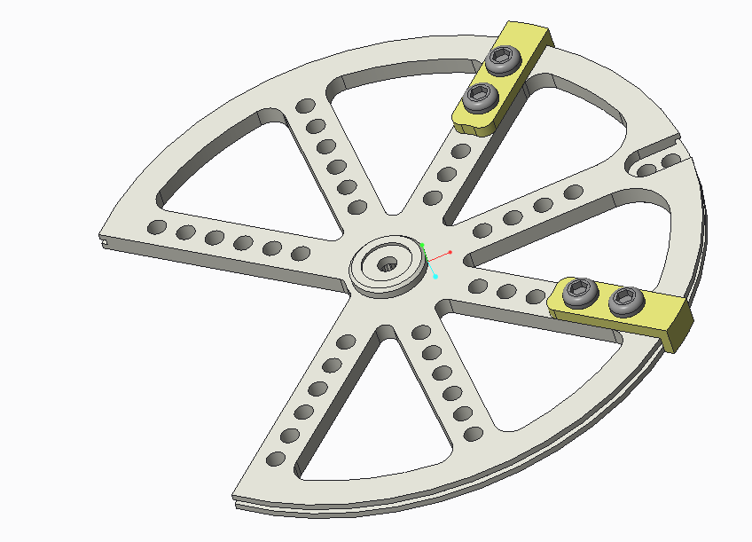
- cable guards preclude the cables *totally* slipping out of the groove due to misalignment