Folks often don't realize the stock JR-type radio connector is only rated at 3.5A. While this was plenty for joining two servos together into one channel back in the day when servos drew 150mA or maybe 250mA, fast forward 30 years and nowadays, individual servos easily draw 2-3A to pairing two together means the combine for more than the 3.5A rating of the connector. Oops!
Anyway, pairing two servos on one channel is still OK for models where individual servos don't draw much current (they exist) but before you do this, check the specs and see what the draw can be because if you make a mistake, it may mean crashing a model.
Meanwhile, modelers hoping radio system manufacturers will put their heads together on a better connector (one rated at more than 3.5A, like maybe 30A, aka a solution) better not be holding their breath. Why not? Simple, it's because competitive market pressures still see them doing what they can to fragment the market, instead. By this meaning they're all seeking advantage at the expense of others the same as a bunch of crabs in a bucket will pull down the one about to get away - fact, look it up. Sadly, the RF manufacturers seemingly won't put their heads together and agree on a standard everybody would benefit from. Sigh.
In the meantime, we at ProModeler work to offer innovative ways to bring additional juice into your model's receiver using the tools at hand. How? We're going to show you how to double up where possible. How? By using batteries or BEC with multiple discharge connectors plus, when you're out of available channels, an ordinary Y-harness!
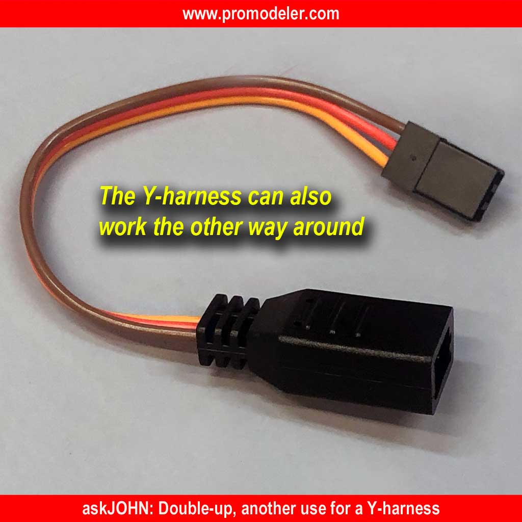
- This sweet looking ProModeler Y-harness is molded to reduce the rat's nest
ProModeler was first to offer battery packs with two leads. This was back in 1983. This innovation remains popular with prudent modelers who continue to recognize the risk to their model of relying on a single on-off switch for the receiver/servos (the avionics).
Basically, running two switches in parallel reduces risk because odds of both switches failing on a single flight are astronomical. Others have begun copying us and honestly, we don't mind!
The point being, if you opt for a pack from someone else, and it's equipped with two leads, then that's fine by us because we'd rather see everybody enjoying the sport more safely.
However, the fact we introduced it first doesn't mean we're standing still because now we've added a 30A connector to your packs, also!
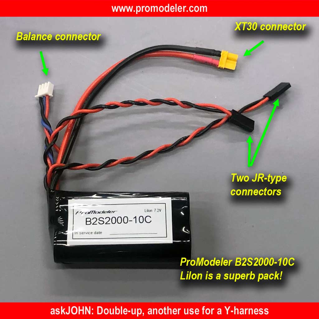
- An XT30 connector increases the versatility of the popular B2S5000-10C
So while our twin-lead batteries remain a top selling product amongst the most savvy of modelers worldwide, we've now added a third discharge connector to the mix. And instead of opting for a proprietary solution, we went to the open market for the nifty Amass XT30 (the 30 meaning it's capable of handling 30A). People use these everywhere, even for connecting high power speaker systems so they're dirt cheap and widely available.

Background
Meanwhile, back in the day our purpose of having two leads was to allow using two on/off switches - this to avoid the single-point of failure that could trash your model in a crash. These days, two leads gives you another important benefit. Basically, two leads, each rated at 3.5A continuous allow you to deliver 7A of current to the receiver with no heat build up. And as it turns out, 7A is enough for virtually all models - sweet!
So why is this important? It's because even a small 3D 48" wingspan model of Extreme Flight Extra NG aircraft equipped with four of our DS105CLHV sub-micro servos may easily push the current handling capability of a single JR-type connector to the limit! Yet another example is someone driving a heavy powerful rig like a Traxxas TRX4 equipped with a single DS505BLHV servo for steering plus a DS75CLHV for the shifter and even the steering servo alone can push that JR-type connector (technically a DuPont connector) beyond the limit!
And herein lies an issue, especially for folks driving those über popular trucks, the receiver may not have an open port where you can add a second power lead. Fortunately, the nifty little Y-harness - most often thought of being used to drive two servos with one channel - comes to the rescue. And the best part is it qualifies as a low-buck solution to your problem!
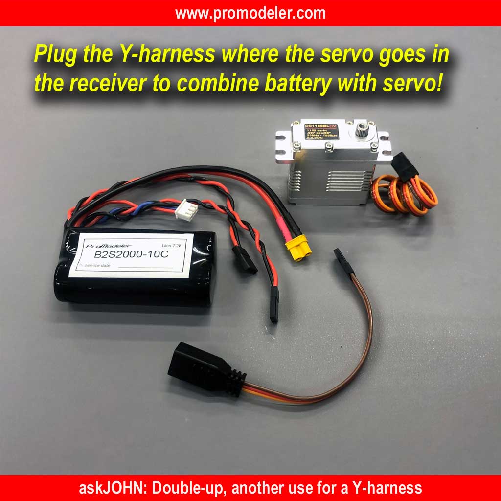
- Connecting a Y-harness to the receiver lets you hook up battery and servo!
This Y-harness trick works in reverse because a radio receiver (if you pull it out of the plastic case and look) demonstrates a perfect example of a bus for powering the servos. This just means the signal-pins (S) are isolated from each other while the (-) pins are interconnected and the (+) pins are interconnected. Using even with a cheapo volt-Ohm-meter let's you prove this for yourself. Let's see how!
As usual, the first thing you do when using an Ohm-meter is to touch the probes to each other and confirm you see 0O, or a short circuit. And if you'll allow me a brief birdwalk, O is the Greek symbol Omega, and it stands for resistance. Resistance is measured in Ohms and the Greek symbol for Omega (O) is used for the SI-derived unit of electrical resistance (named after German physicist Georg Ohm). Now back our lesson for the day!
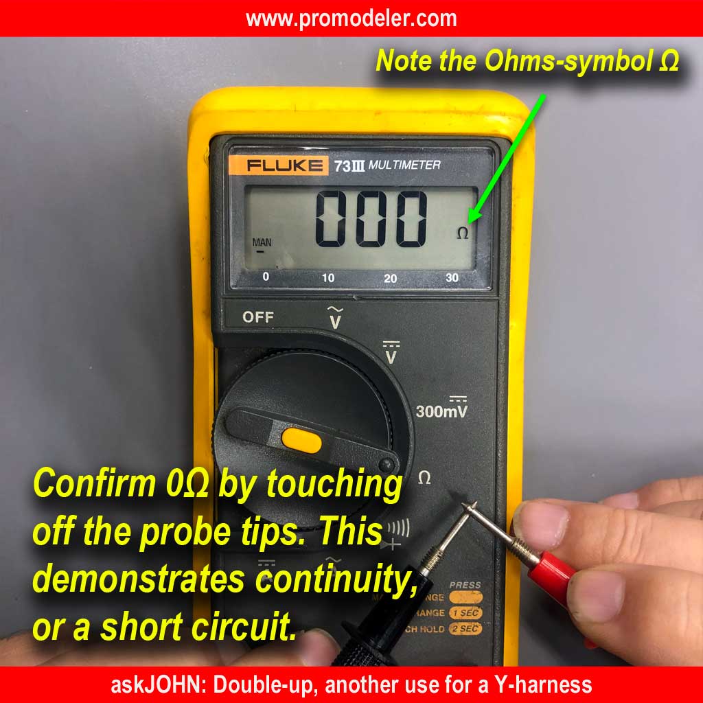
- If you're a lifer, it pays to invest in good tool like a good volt-Ohm-meter
Meanwhile, it you check connectivity the signal pins of the receiver, you're going to find an open loop between each. This means they do not connect to each other - ever! And when you look at your meter, the reading will indicate an open circuit usually as OL for (Open Loop), or perhaps infinity (8) on some meters. Both mean the same thing, no connection!
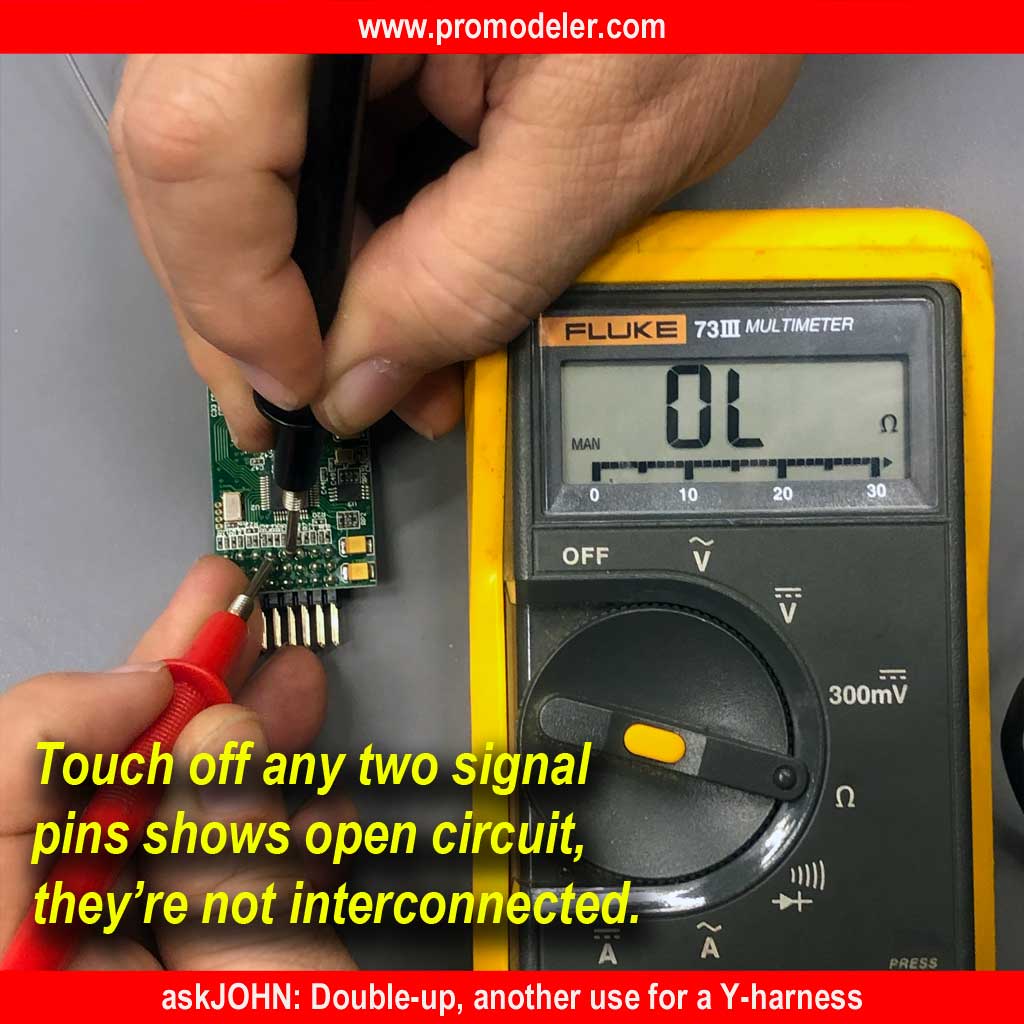
- OL means Open Loop and this means there's no interconnection - none!
Earlier I mentioned the (+) pins are interconnected as are the (-), which interconnect to each other as well [but the (+) and the (-) are isolated from each other, of course, else everything goes up in smoke]. In this instance, when you touch the probes of your meter to either two (+) pins or two (-) pins, you get connectivity, or 0 Ohms of resistance.
On this receiver I'm measuring between any two (+) pins and I see 0O. This means a perfect short circuit, or meaning that the two pins are connected somewhere. The 'somewhere' doesn't really matter. The fact is they are interconnected. Ditto the (-) pins.
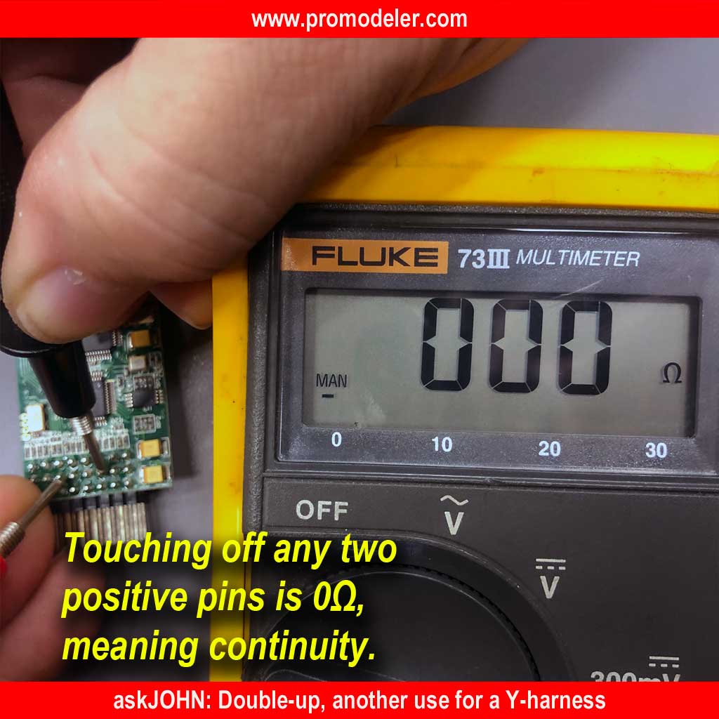
- Connect any two (+) pins and seeing 0O proves there is connectivity of all
Anyway, the point of all this is, you don't have to connect the battery to where it's silk-screen (or otherwise marked) BATT for battery, but can instead connect it anywhere you have a free channel port - nice, eh? What's this really mean? Well, as a practical matter it means you can use a Y-harness to deliver juice 'to' your receiver even if all the channels are filled (or assigned) by servos!
Bottom line? Becoming a professional modeler merely involves thinking like pros . . . or put another way, always looking for an advantage by thinking outside of the box!
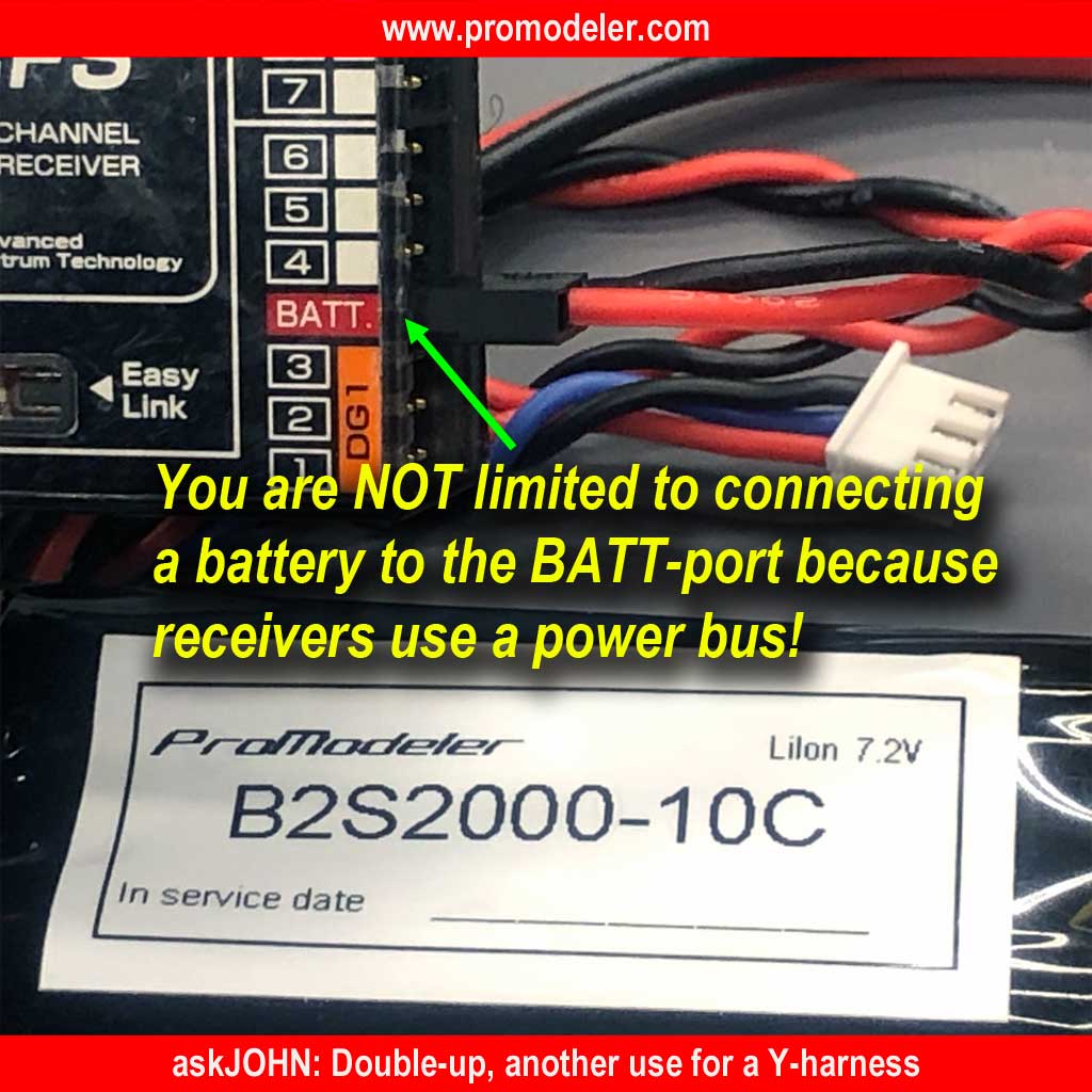
- Avoiding limits set by others is all in the mindset - it's the ProModeler way!
So if you want to use a better battery (one, by definition equipped with more than one lead for added versatility), and your receiver's channels are all full, then the trick of using a Y-harness in the reverse direction is an easy way to go about it.
Basically, you just connect your Y-harness to any occupied channel of the receiver (e.g. where there's a servo already connected), and at the other end, connect both a battery lead and the same servo. Voltage flows to the power bus from the battery and is also drawn by the servo at the same time. Win-win and as usual with ProModeler, we try to make things easy-peasy!
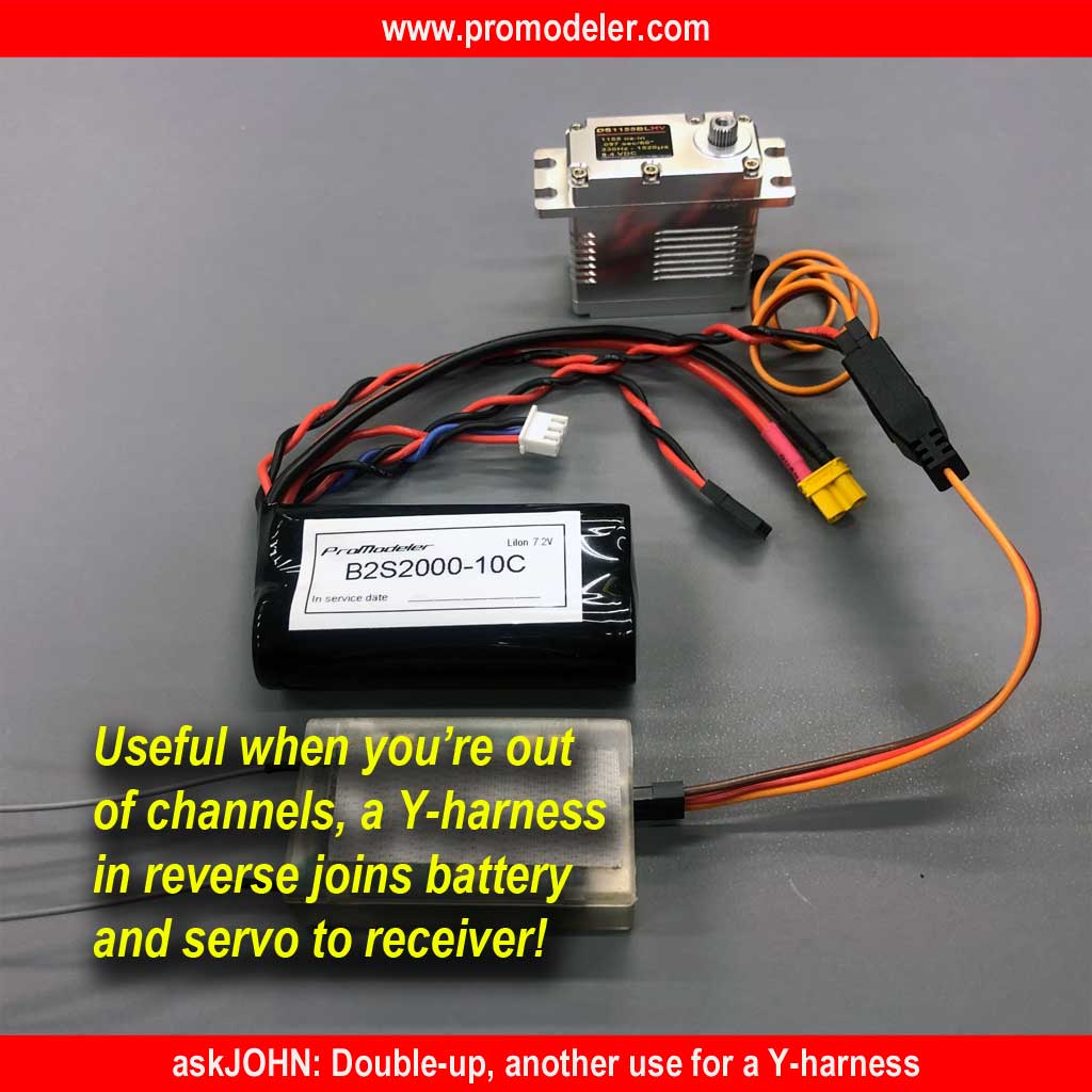
- Easily connect a battery lead *and* a servo to any channel at your receiver!